Condition Monitoring Blog Data Centers Electrical
TL;DR: The Most Expensive Electrical Failures Usually Start Small
Most industrial electrical failures are not sudden. They begin as small thermal and resistance changes inside energized infrastructure that no one is continuously watching.
Key takeaways:
-
Loose electrical connections often generate heat for days or weeks before a breaker trips.
-
Periodic thermography misses many load-dependent and intermittent faults.
-
MCCs, switchgear, VFDs, and distribution panels create the highest operational blast radius when they fail.
-
Continuous condition monitoring captures progressive degradation before it becomes downtime.
- Multi-sensor corroboration improves alert confidence and reduces false escalations.
- The goal is not simply detecting faults after alarms trigger. It is creating enough detection window to intervene during planned maintenance instead of emergency downtime.
The Most Expensive Electrical Failures Are Usually the Ones Nobody Saw Developing
A switchgear termination runs hot under load for weeks. No alarm fires. The first visible symptom is an unplanned shutdown that takes a production line offline for six hours.
An MCC cabinet supplying four conveyor drives starts generating intermittent nuisance trips. Each trip clears on reset. Three weeks later, a bus bar overheats and shuts down the entire conveyor zone.
A VFD repeatedly throws nuisance fault codes. Cooling fan degradation slowly raises cabinet temperature, but no threshold alarm triggers. The drive fails during peak production.
These failures rarely happen without warning. The problem is that the warning signals develop inside energized infrastructure — in places reliability teams cannot continuously see and systems were never designed to monitor.
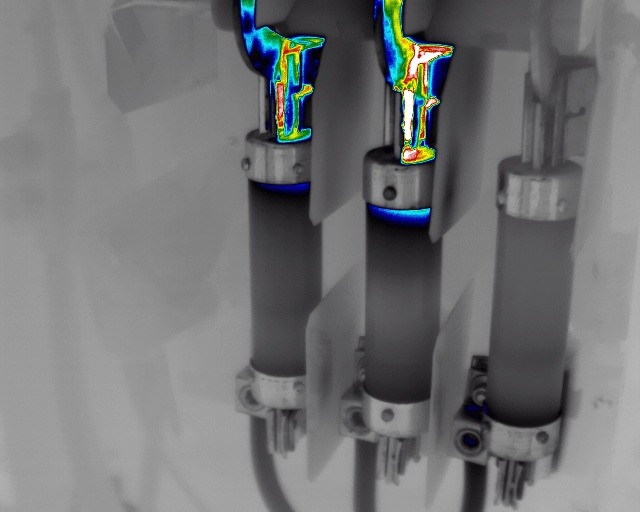
 Localized resistance heating at a switchgear connection point can develop for days before triggering a breaker trip.
Why Industrial Electrical Failures Become So Expensive
Electrical infrastructure is upstream of almost every automated industrial process. When a failure occurs:
- A switchgear trip can remove power from multiple downstream systems simultaneously.
- An MCC cabinet failure can disable every conveyor, motor, or drive it feeds.
- A VFD failure in a sortation system can idle labor and starve downstream automation within minutes.
The operational consequence rarely stays local. This is what defines blast radius: the scope of disruption created by a single electrical failure.
The financial exposure is not abstract. In distribution environments, unplanned downtime runs approximately $10,000 per hour. In sortation operations, that figure rises to $10,000–$50,000 per hour, depending on throughput volume and SLA commitments. When an MCC cabinet or VFD failure takes down multiple conveyor zones simultaneously, the clock starts immediately — and the labor, recirculation, and carrier penalty costs compound beyond the downtime hour itself.
The cost of the repair is rarely the primary expense. What drives the bill is the difference between a planned intervention and a reactive one. Industry benchmarks consistently show that reactive maintenance costs 3–5 times more than the same work performed on a planned basis, driven by emergency labor rates, expedited parts procurement, and extended downtime while the operation waits for resolution. The failure mode does not change. The detection timing does — and that timing determines which column the costs land in.
The Industrial Electrical Failures That Usually Create the Highest Costs
1. Loose and High-Resistance Electrical Connections
Loose terminations are among the most common and underdetected electrical failure modes in industrial environments. Resistance at a degraded connection generates localized heat that progresses through a predictable sequence: loose termination → resistance heating → insulation degradation → breaker trip or arc fault → downstream outage.
Key detection signals include localized hot spots at terminals or bus bars, temperature delta between comparable phases, and progressive thermal drift under normal load. Because this progression can unfold over days or weeks with no visible symptom and no PLC alarm, periodic inspection misses it routinely.
2. Overloaded Circuits and Phase Imbalance
Phase imbalance and sustained overload accelerate insulation aging and place uneven thermal stress on motors and downstream equipment. The failure progression follows a predictable path: phase imbalance → uneven heating → insulation degradation → motor or equipment failure.
The damage accumulates gradually. By the time a motor trips or fails, the insulation may have been degrading for weeks. Early thermal trending identifies which phases are running hot before that degradation becomes irreversible.
3. VFD and Control Panel Degradation
VFDs contain heat-sensitive components in enclosed environments where degradation progresses silently. Cooling fan decline is a common initiator: cooling fan degradation → cabinet temperature rise → capacitor or IGBT stress → nuisance trips → drive failure.
Continuous monitoring correlates trip history with rising cabinet temperature, making the failure trajectory visible before the drive goes down.
4. MCC Cabinet and Switchgear Arc Fault Risk
MCC cabinets and switchgear assemblies represent some of the highest-consequence electrical failure points in industrial environments. A single cabinet can supply power to multiple conveyor zones, motor control circuits, or production lines simultaneously. When it fails, the blast radius is immediate and wide.
The failure pathway typically begins with a loose bus bar connection or degraded contact surface generating resistance heating under load. That heat progresses toward insulation breakdown. If undetected, the result is an arc fault event, an unplanned multi-zone outage, and potential fire risk. NFPA data shows that electrical distribution equipment accounts for 18% of U.S. warehouse structure fires and 31% of direct property damage, averaging $283 million annually.
Fixed thermographic monitoring detects thermal buildup at bus bar junctions and connection points before fault thresholds are reached, typically providing 24 to 48 hours of lead time before a cabinet shutdown, based on MSAI deployment data.
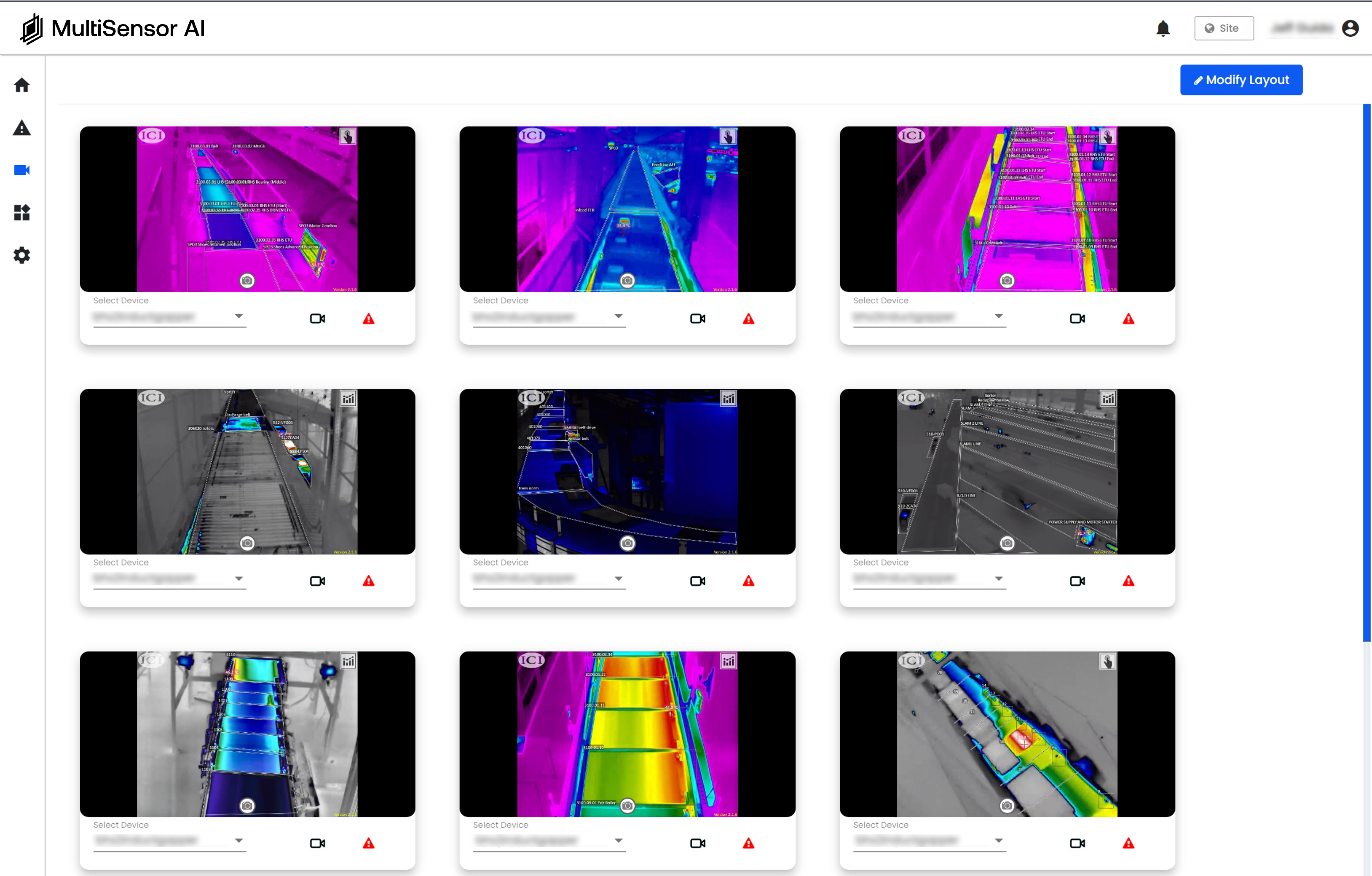
 Electrical infrastructure failures create operational disruption far beyond the failed component itself.
Why Periodic Inspections Usually Miss Early Electrical Degradation
Manual thermography is a snapshot. A monthly inspection captures equipment condition at one operating state, which may not coincide with the asset's highest-risk condition. Many electrical faults are load-dependent: they intensify under heavy production and moderate during low-activity periods. A scheduled inspection during light load may record normal temperatures on an asset running dangerously hot four hours later.
SCADA and OEM alarms confirm fault states. They are not designed to identify early degradation.

Many electrical faults develop between periodic inspections, creating a visibility gap where thermal degradation progresses unnoticed until operational failure occurs.
What Continuous Condition Monitoring Changes
Fixed monitoring captures data continuously across all operating conditions. Progressive thermal drift becomes visible before it reaches fault thresholds. Intermittent anomalies are recorded historically, not just at the moment of inspection. Load-dependent faults are captured when they occur. Environmental shifts are correlated with asset behavior over time.
The result is a detection window: time between when the signal first appears and when the failure would otherwise occur. That window is what converts emergency downtime into planned maintenance.
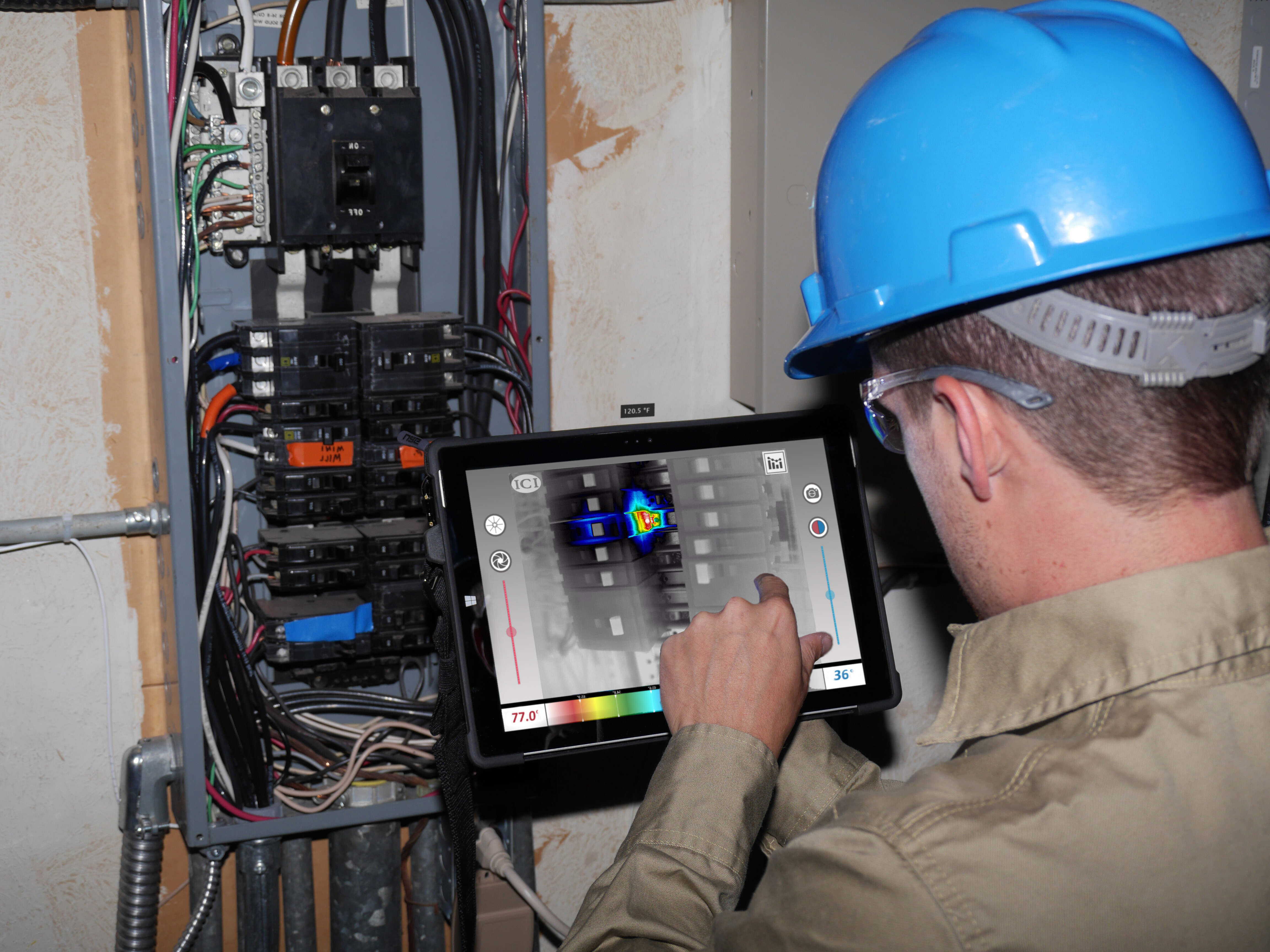
Continuous thermal trending reveals degradation progression before operational failure occurs.
A Practical Framework for Getting Ahead of Expensive Electrical Failures
- Identify the highest-consequence electrical assets: switchgear, MCCs, VFD panels, and distribution boards feeding non-redundant equipment.
- Establish normal thermal baselines across operating conditions and load profiles.
- Monitor for drift, not just threshold crossings. Trend direction matters as much as current temperature.
- Correlate multiple signals before escalating. A single temperature spike may be normal; a rising trend across shifts is not.
- Intervene inside the detection window. Plan the repair before the asset forces the issue.
- Confirm post-repair return to baseline. Validate the intervention resolved the underlying condition.
Most expensive industrial electrical failures begin as small thermal and resistance changes inside energized infrastructure. The economics of failure are determined by detection timing. Early detection converts emergency downtime into planned maintenance — and planned maintenance costs a fraction of reactive response.
Related Resources
- Electrical Fault Detection for Motors, Panels & Switchgear
- Condition Monitoring System — MSAI Connect
- Rotating Equipment Monitoring
- Condition Monitoring for Data Centers
FAQ
What industrial electrical failures usually create the highest downtime costs?
Failures involving switchgear, MCC cabinets, and VFD systems typically create the highest operational impact because they supply power to multiple downstream systems simultaneously. A single cabinet failure can disable entire conveyor zones or production lines at once.
Why are loose electrical connections so dangerous?
Loose connections generate localized resistance heating that develops silently inside energized infrastructure. There is no visible symptom and no PLC alarm until the fault reaches a threshold that triggers a trip or arc. By that point, insulation damage has often already occurred.
Why do periodic thermal inspections miss some electrical faults?
Periodic thermography captures only one operating condition at one moment in time. Many electrical faults are load-dependent and intensify under heavy production. A scheduled inspection during off-peak hours may record normal temperatures on an asset running dangerously hot during peak operations.
What is the biggest advantage of continuous electrical condition monitoring?
The biggest advantage is earlier detection timing. Continuous monitoring captures thermal drift and anomalies across all operating conditions, not just during inspection windows. That detection lead time is what allows intervention before failure.
Keep reading

MSAI Connect Thermal Monitoring Condition Monitoring Blog Vibration
You Have Condition Monitoring—But Here's What It's Probably Missing
Condition Monitoring Blog Data Centers Electrical