Condition Monitoring Blog Data Centers
TL;DR — Redundancy Does Not Eliminate the Visibility Gap
Data center redundancy protects uptime, but it can also hide degradation until UPS transfers, generator starts, switchgear bypasses, or cooling failovers force systems into a different operating state.
- Redundant systems can mask degradation until backup infrastructure is exercised under real load.
- The highest-risk moments are often transient events, not steady-state operation — though many degradation modes develop continuously and become more visible, not exclusively visible, during switchovers.
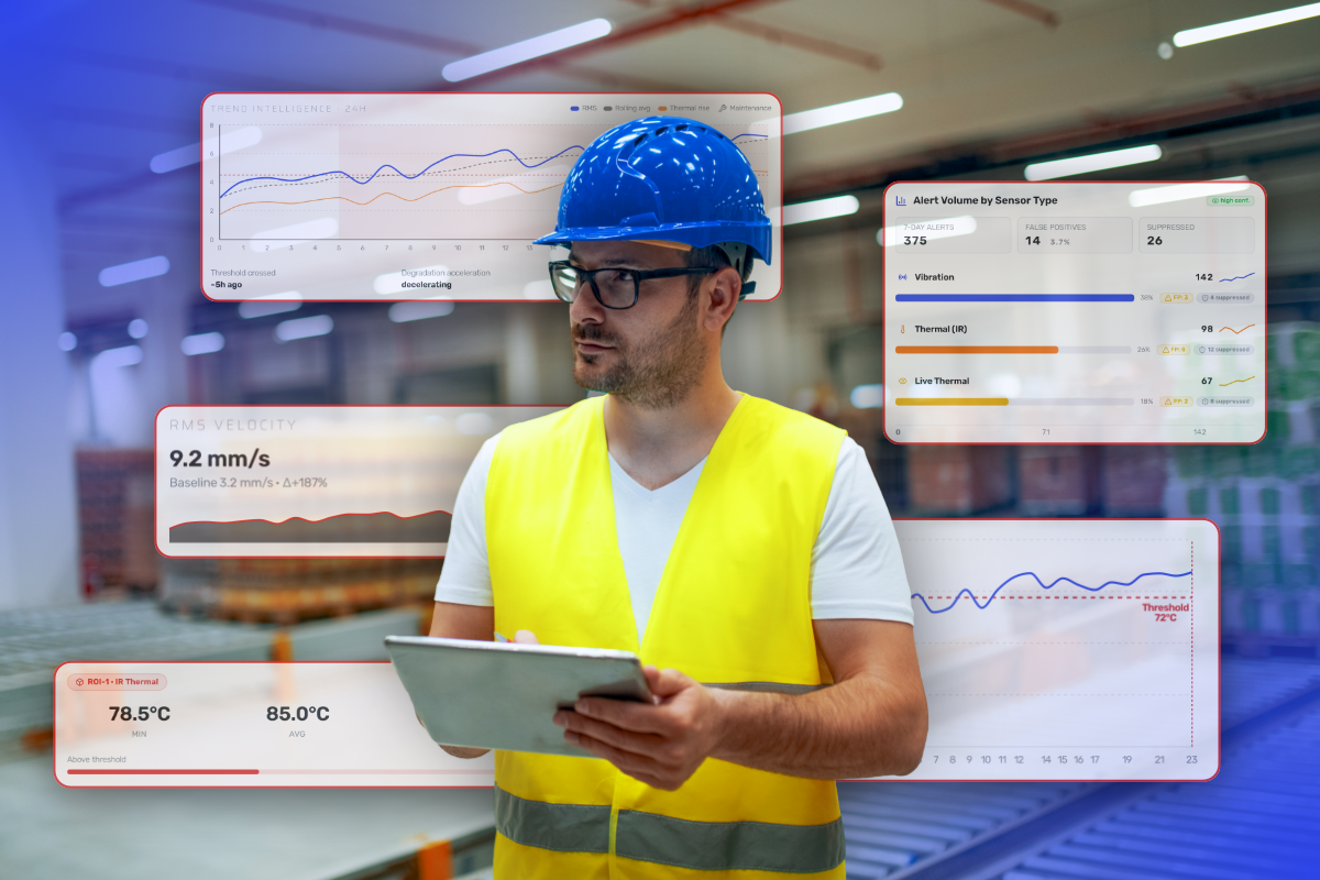
- Periodic thermography, BMS alarms, and OEM dashboards rarely provide the thermal, vibration, visual, and environmental context needed to explain what changed or when degradation began.
- Condition monitoring gives operators visibility before, during, and after switchover events so they can validate risk, monitor abnormal behavior, and support root cause analysis.
- The goal is not to replace BMS, DCIM, SCADA, or CMMS. The goal is to add a condition intelligence layer above them.
For data center operators, the question is not only whether the system transferred. It is whether the system transferred cleanly, without hidden electrical, mechanical, thermal, or environmental degradation.
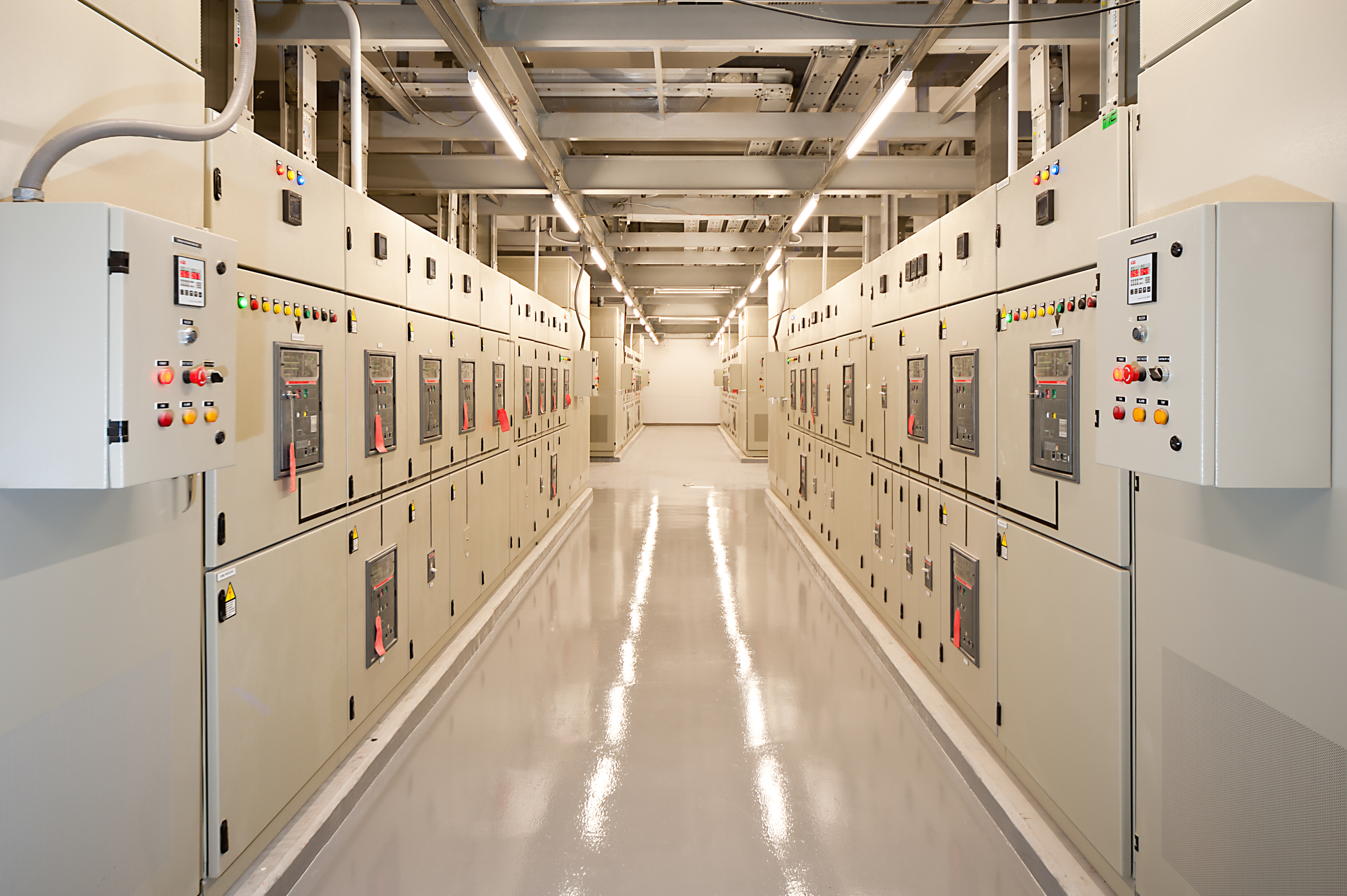
The Problem with Data Center Redundancy Is Not the Switchover — It Is What You Cannot See During It
A UPS system transfers load during maintenance and one downstream PDU shows unexpected thermal rise. A generator start sequence completes, but vibration on an associated cooling pump or fan increases under the new load condition. A maintenance bypass is engaged, but switchgear temperature patterns look different from the last bypass event.
Cooling may also shift to redundant capacity while a chiller, pump, or CRAH/CRAC fan behaves differently under transient demand. The BMS may still show “normal,” but facilities teams still do not know whether the event introduced residual risk.
This is the core visibility problem in modern data centers.
Redundancy protects uptime, but redundancy does not automatically make degradation visible. In many facilities, it does the opposite: it hides weak components until a switchover, failover, or bypass event exposes them under changed operating conditions. Some of those fault types, particularly resistance-based electrical faults, only produce a detectable thermal signature under specific load paths. Others are progressing continuously in the background but become more pronounced when operating conditions change.
Condition monitoring in data centers is not only about finding failures during steady-state operation. It is about understanding how electrical and cooling systems behave when redundancy is exercised — and maintaining the continuous baseline that makes transient deviations recognizable.

Data center redundancy events affect interconnected power, cooling, environmental, and control systems simultaneously, which is why multi-sensor condition monitoring is critical for understanding how infrastructure behaves during switchovers and failovers.
Why Data Center Visibility Breaks Down During Redundancy Events
Redundancy can mask weak components
N+1 and 2N architectures improve resiliency, but they can also conceal degradation because systems are not stressed equally during normal operation.
Standby UPS modules may appear healthy until transfer. Backup generators may pass periodic load testing but behave differently under sustained operational load — particularly when runtime extends beyond test duration, ambient temperatures deviate from test conditions, or fuel system components are approaching wear thresholds. Generator thermal and vibration signatures under sustained load are legitimate monitoring targets that periodic short-duration tests do not capture. Switchgear sections, PDUs, breakers, fuse holders, and busbar connections may only develop abnormal thermal patterns after electrical load paths change.
The same applies to cooling infrastructure. Pumps, chillers, cooling towers, CRAH/CRAC units, and cooling fans may look stable until pressure, flow, or duty cycles shift during a failover event.
This creates three major visibility gaps:
- Temporal gaps, where degradation appears or intensifies between inspection cycles.
- Modal gaps, where a single sensor type provides incomplete context.
- Organizational gaps, where information remains siloed across systems and teams.
- Localized heating at a loose termination below alarm threshold.
- Thermal drift in a PDU, UPS cabinet, or switchgear section.
- Vibration deviation on a cooling pump or fan.
- Environmental changes around electrical rooms or cooling infrastructure.
- Visual evidence of abnormal operating state during an event.
BMS and DCIM alerts are not condition signals
BMS and DCIM systems are essential operational tools, but they are not designed to identify every early-stage degradation pattern.
They may not detect:
This distinction matters because operational systems confirm status, while condition monitoring reveals degradation. The gap between a system that is “operationally normal” and one that is approaching failure can be hours or days wide, and it is invisible to threshold-based alarm systems until the failure crosses a defined boundary.
MSAI augments BMS, CMMS, SCADA, and DCIM systems by adding thermal, vibration, visual, and environmental condition intelligence across critical infrastructure.
Why Periodic Inspections Fail During Switchovers, Failovers, and Bypass Events
Inspections capture a moment, not the event
The fundamental limitation of periodic inspection is structural, not a matter of technician diligence. For a condition-based inspection to reliably detect a developing failure, the inspection interval must be shorter than the P–F interval of the failure mode in question — and short enough to leave time to act on the detected signal before functional failure occurs. This principle, formalized in reliability-centered maintenance theory, makes the limitation of calendar-based inspection mathematically explicit: when inspection frequency does not match the progression rate of a failure mode, detection depends largely on chance.
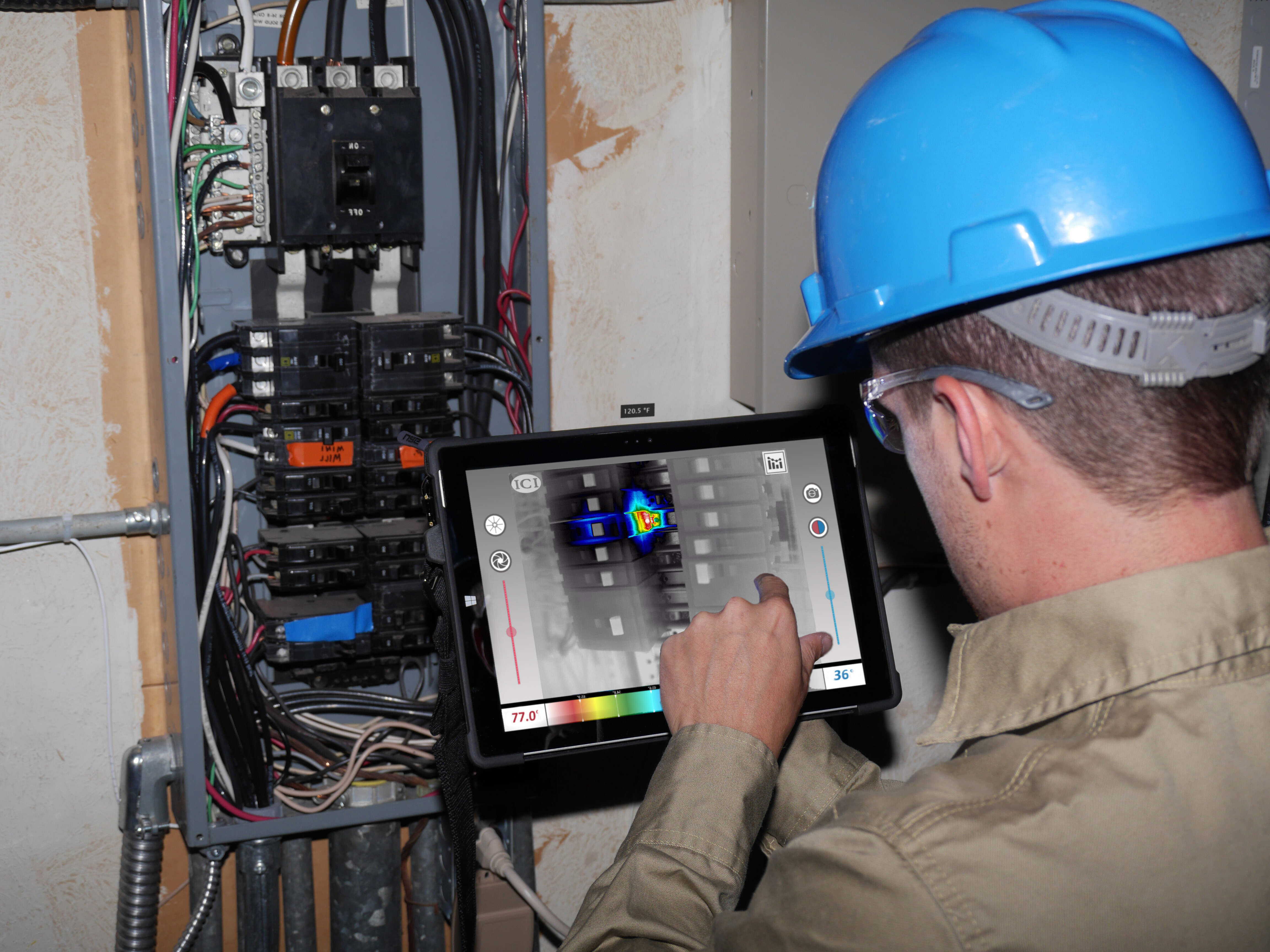
Manual thermography and inspection routes often happen before or after the event, not during the most important transient operating window. Load conditions change quickly. Thermal rise may appear and normalize before the next inspection route. Vibration deviations may only occur during transfer or ramp-up. Operators may not have visual or thermal context when reviewing the event afterward.
For fault types that are load-path-dependent — resistance-based electrical faults, in particular — the thermal signature may only become detectable when current flows through the degraded connection under changed conditions. No inspection performed during steady-state operation will find what is only visible during a switchover.
Single-sensor monitoring creates partial confidence
Thermal-only monitoring may show heat but not confirm whether the source is electrical resistance, airflow restriction, load imbalance, or mechanical friction. Vibration-only monitoring may reveal movement but miss electrical distribution risk. BMS alarms may show operational status but not localized degradation. OEM dashboards may isolate data by asset type.
Signal interpretation and multi-sensor corroboration are what turn raw signals into actionable operational intelligence. A thermal anomaly on a cooling pump, for example, requires vibration data and motor temperature context to distinguish bearing wear from cavitation, hydraulic imbalance, or resonance at a new operating point.

Periodic inspections capture only isolated moments in time, while continuous condition monitoring helps data center operators detect developing thermal anomalies before they escalate into operational failures during redundancy events.
What Is Actually Happening During Data Center Redundancy Events
Electrical load paths change
Switchovers and bypass events alter current flow through UPS systems, switchgear, PDUs, busbars, breakers, and downstream electrical panels.
Potential failure progression:
Loose termination → localized resistance heating → thermal anomaly during load transfer → breaker stress or trip risk.
This failure mode is load-path-dependent: the degraded termination may produce no detectable thermal signature during normal operation, becoming visible only when current is routed through it under changed conditions. It is also entirely silent to PLC-level alarms until a trip threshold is reached.
Detection signals include:
-
Temperature delta across similar components.
-
Localized hot spots on busbars, breakers, terminals, or fuse holders.
- Thermal rise appearing during transfer or bypass that was not present under the previous load path.
- Visual context around affected cabinets or connection zones.
Cooling load shifts
Failovers redistribute thermal burden across chillers, pumps, cooling towers, CRAH/CRAC units, fans, and valves.
Potential failure progression:
Pump degradation → vibration deviation under changed duty cycle → reduced cooling performance → thermal instability in the supported zone.
The specific cause of vibration deviation on a pump under changed duty requires multi-sensor corroboration to diagnose accurately. Possibilities include bearing wear, cavitation under altered flow conditions, hydraulic imbalance, impeller wear, or resonance at the new operating point. Monitoring identifies the signal; investigation determines the cause.
Detection signals include:
- Vibration deviation on pumps or fans.
- Thermal trend changes around cooling equipment.
- Environmental temperature or humidity drift.
- Abnormal motor temperature under load.
Control and drive behavior changes
VFDs, PLCs, control panels, and motor-driven systems supporting power and cooling infrastructure may behave differently during transient load conditions.
Potential failure progression:
VFD degradation → inconsistent motor speed response → cooling instability → repeated nuisance alarms or reduced redundancy confidence.
Detection signals include:
- Control panel thermal rise.
- Motor temperature deviation.
- Vibration changes under variable load.
- Event-specific abnormal behavior not present during steady-state operation.

Data center cooling infrastructure must remain stable during switchovers and failovers, making continuous condition monitoring critical for identifying thermal drift, airflow issues, and developing mechanical degradation before redundancy is compromised.
How Continuous Condition Monitoring Improves Visibility Before, During, and After Data Center Redundancy Events
Before the event: Validate risk before exercising redundancy
Before planned switchovers, failovers, or bypass events, teams should review condition signals across:
- UPS cabinets and battery systems.
- MV/LV switchgear.
- PDUs and distribution panels.
- Backup generators.
- Chillers, pumps, fans, and cooling towers.
- Control cabinets, VFDs, and PLCs.
Teams should look for:
- Thermal anomalies.
- Temperature drift from baseline.
- Vibration deviation.
- Abnormal environmental conditions.
- Asset-to-asset differences across redundant systems.
The operational value is simple: de-risk the decision before changing system state. Continuous monitoring that has been running for weeks or months provides a behavioral baseline against which pre-event condition signals can be evaluated with confidence.
During the event: Control transient risk in real time
Continuous monitoring provides visibility while conditions are actively changing. Teams should monitor for:
- Rapid thermal rise at electrical connections.
- Abnormal heat buildup in UPS, PDU, switchgear, or bypass panels.
- Cooling fan or pump vibration deviation.
- Environmental drift in supported rooms or zones.
- Secondary effects caused by load transfer.
The goal is to identify abnormal behavior while there is still time to intervene.
After the event: Preserve context for root cause analysis
Condition monitoring should help teams answer:
- Which asset changed first?
- Was the issue electrical, mechanical, environmental, or control-related?
- Did the system return to baseline?
- Did the event create residual risk?
- Should operating procedures, inspection routes, or design assumptions change?
This supports MSAI’s data center monitoring narrative: detect, control, learn.

MSAI Connect provides continuous thermal monitoring and anomaly detection visibility across critical infrastructure, helping operators identify developing electrical and mechanical degradation before redundancy events become operational failures.
What Signals Matter Most in Data Center Condition Monitoring
Thermal signals
Thermal monitoring is critical for:
- Switchgear
- UPS systems
- PDUs
- Electrical panels
- Busbars
- Breakers
- Fuse holders
- Battery systems
- Control cabinets
Key indicators include localized hot spots, temperature delta between phases, thermal drift during bypass, and heating that appears only under changed load paths. The last of these is the signature of resistance-based electrical faults: invisible during normal operation, detectable when the current path changes.
Vibration signals
Vibration monitoring is critical for:
- Chiller motors
- Pumps
- Cooling fans
- Generator-related rotating equipment
- HVAC support systems
Teams should monitor for:
- New vibration deviation during failover.
- Increased vibration under changed load.
- Intermittent anomalies that do not appear during steady-state checks.
Vibration signals require corroboration from thermal and environmental data before a root cause diagnosis can be made. A deviation in isolation identifies a condition worth investigating, not a confirmed failure mode.
Visual signals
Visual monitoring helps validate:
- Event timing
- Cabinet state
- Equipment position
- Environmental context
- Asset condition before and after intervention
Visual context also helps teams understand alarm timing and operational state during transient events, and provides an audit record when reviewing what changed and when.
Environmental signals
Environmental monitoring is important for:
- Electrical rooms
- Mechanical rooms
- Cooling zones
- Generator rooms
- Temperature drift.
- Humidity change.
- Localized airflow issues.
- Room-level changes following load transfer.
 Data center operators often rely on BMS and DCIM platforms for system status visibility, but condition monitoring adds deeper thermal, vibration, visual, and environmental insight into developing infrastructure degradation.
Teams should monitor:
- Temperature drift.
- Humidity change.
- Localized airflow issues.
- Room-level changes following load transfer.
Where Current Monitoring Approaches Usually Fall Short
BMS/DCIM systems show status, not always degradation
Operational systems are essential, but they are not designed to identify early-stage physical degradation. They confirm that a system is running; they do not measure whether it is running well.
Manual thermography misses transient windows
A monthly or quarterly inspection may not coincide with the switchover or bypass event where abnormal behavior becomes detectable. For load-path-dependent faults, an inspection performed during normal operation may return a clean result for a component that would show a clear thermal anomaly the moment load conditions change.
OEM monitoring is often siloed by asset
UPS systems, generators, chillers, and switchgear often exist inside separate monitoring environments without unified event visibility. The first sign that a redundancy event has introduced risk may be a nuisance alarm in a system that no one is correlating against anything else.
Alarm thresholds often trigger too late
Threshold alarms frequently activate after degradation has already progressed. This is structurally true of any threshold-based system: the alarm is calibrated to a fault state, not to the early degradation phase where intervention is least costly.
Effective condition monitoring addresses this by establishing a behavioral baseline and detecting deviations from it, rather than waiting for a fixed threshold to be crossed.

Different maintenance strategies provide different levels of reliability and risk reduction, but condition-based monitoring gives data center operators earlier visibility into developing degradation before redundancy events expose critical infrastructure weaknesses.
A Practical Framework for Critical System Visibility During Redundancy Events
|
Step 1: Map the event path |
|
Step 2: Identify single points of consequence |
|
Step 3: Establish pre-event baselines |
|
Step 4: Monitor transient behavior during the event |
|
Step 5: Compare return-to-normal after the event |
|
Step 6: Use event history to improve the next procedure |
Scenario 1: Maintenance Bypass Reveals a Hidden Switchgear Issue |
SituationA regional colocation data center schedules a UPS maintenance bypass. Pre-event checks show no active BMS alarms. During bypass, fixed thermal monitoring detects localized heating on one switchgear termination. The temperature delta rises only after the load path changes. What would have been missedA manual inspection two weeks earlier showed no issue because the affected connection was not under the same load condition. The fault was load-path-dependent: invisible to periodic inspection performed during normal operation, and entirely absent from BMS alarms until it reached a trip threshold. Signal progressionLoose termination → resistance heating during bypass → localized thermal anomaly → elevated trip and equipment damage risk. ActionThe team exits the bypass procedure, investigates the switchgear section, and schedules corrective work during a controlled window. ResultsThe bypass event is stopped before abnormal heating becomes a trip, equipment damage, or fire-risk event. The team converts a potentially high-risk electrical fault into planned corrective action. |
Scenario 2: Cooling Failover Exposes Pump Degradation |
SituationA hyperscale facility shifts cooling load during planned chiller maintenance. The BMS confirms the backup path is active, but vibration monitoring shows abnormal deviation on a redundant pump. Thermal monitoring also shows motor temperature rising faster than comparable pumps. Signal progressionPump degradation → vibration deviation during increased duty → motor heat increase → cooling reliability risk. Diagnostic noteThe corroborating signals — vibration deviation plus abnormal motor temperature increase — narrow the likely causes. Bearing wear and impeller degradation are the leading candidates given the signature. Cavitation would typically produce a distinct acoustic profile; hydraulic imbalance would be expected to appear at lower duty cycles as well. Investigation and inspection confirm the diagnosis before any corrective action is taken. ActionThe team keeps the system stable, flags the pump for inspection, and compares post-event trends to determine whether the pump returned to baseline. ResultsThe cooling failover remains stable, but the event exposes a degraded redundant pump before it becomes a bottleneck during an unplanned outage. |
Redundancy Events Need Condition Visibility, Not Just System Status
Switchovers, failovers, and bypass events should be treated as risk-revealing moments, not routine operating sequences. A completed transfer does not automatically mean the system is healthy. It means the system transferred. Whether it transferred cleanly, without introducing new risk or exposing latent degradation, is a different question — and one that BMS and DCIM platforms alone are not designed to answer.
Industry data on post-transfer fault discovery is limited, but the failure physics are well-established: resistance-based electrical faults are load-path-dependent and structurally invisible to steady-state monitoring. Rotating equipment degradation becomes more pronounced under changed duty. These are not edge cases; they are predictable consequences of how degradation behaves in redundant systems.
Continuous condition monitoring addresses this by:
- Establishing a behavioral baseline that makes pre-event anomalies visible before redundancy is exercised.
- Capturing transient signals that appear only during load path changes and would otherwise go undetected.
- Preserving post-event context for root cause analysis and procedural improvement.
The most important signals include thermal anomalies in switchgear, PDUs, UPS cabinets, and control panels; vibration deviation on pumps, fans, and chillers; motor temperature drift under changed duty; and environmental changes around cooling zones or electrical rooms.
Before the event, teams validate risk before changeover. During the event, they monitor transient behavior. After the event, they compare return-to-baseline conditions and identify residual risk.
FAQ: Condition Monitoring for Data Center Switchovers, Failovers, and Bypass Events
Why do data centers need condition monitoring if they already have redundancy?
Redundancy protects uptime, but it can also hide degradation. Some fault types, particularly resistance-based electrical faults, only produce a detectable thermal signature when current flows through the degraded path under changed load conditions. Condition monitoring helps teams identify abnormal thermal, vibration, or environmental patterns before redundancy is exercised, and captures the transient signals that appear during events that periodic inspection and BMS thresholds are not designed to catch.
What is the biggest visibility gap during a switchover or failover?
Two gaps matter most. The first is load-path-dependent degradation: faults that are thermally invisible during normal operation but become detectable when current routing changes. The second is transient behavior: vibration deviations, motor temperature rise, and environmental drift that may appear and normalize within the duration of the event, leaving no trace for a post-event inspection to find.
Does condition monitoring replace BMS or DCIM?
No. Condition monitoring augments BMS and DCIM systems by adding thermal, vibration, visual, and environmental condition intelligence. BMS and DCIM confirm operational status. Condition monitoring reveals whether the underlying physical condition of assets is changing.
What systems should be monitored during bypass events?
UPS systems, switchgear, PDUs, electrical panels, backup generators, chillers, pumps, cooling fans, VFDs, PLCs, and control cabinets. Generator behavior under sustained load is a particular area of interest: generators that pass periodic short-duration tests may behave differently when operating at sustained load for extended periods.
What signals matter most during a redundancy event?
Thermal rise and temperature delta at electrical connections are the primary indicators for resistance-based faults. Vibration deviation on rotating equipment is the primary indicator for mechanical degradation, but requires corroboration with thermal and environmental data before root cause conclusions can be drawn. Environmental drift in cooling zones and visual context around affected assets complete the picture.
How does condition monitoring help after an event?
It preserves historical thermal, visual, vibration, and environmental context so teams can identify what changed first, validate return-to-normal conditions, assess residual risk, and improve future procedures. Events handled with monitoring in place build an institutional knowledge base about which assets carry the most risk under specific operating transitions.
Keep reading
MSAI Connect Thermal Monitoring Condition Monitoring Blog Vibration
You Have Condition Monitoring—But Here's What It's Probably Missing
Condition Monitoring Blog Data Centers Electrical