%20type%20electric%20cabinets%20with%20fixed%20shelves.jpg)
Manufacturing Thermal Monitoring Condition Monitoring Blog Electrical
TL;DR - Why Intermittent Electrical Faults in Motor Control Panels Rarely Show Up During Scheduled Inspections
Intermittent electrical faults in MCCs and motor control panels are structurally invisible to scheduled inspections because:
- They develop under operating load and clear at rest, so periodic IR scans capture the panel in its most benign state.
- Loose connections account for over 30% of all industrial electrical failures, and the faults they produce are intermittent and load-dependent.
- A quarterly thermography scan captures one moment. If the fault is dormant during that moment, it will not appear.
- Detection requires continuous thermal observation under operating load, historical baseline trending, and multi-signal context.
Electrical faults in motor control panels rarely start with a dramatic failure. They start with a breaker that trips during a Tuesday afternoon sort window, resets cleanly, and gives maintenance nothing to find. The IR contractor was onsite three weeks ago. The scan came back clean. You logged it as a nuisance trip and moved on.
Two weeks later, the same breaker trips again. Same MCC section, same load conditions, same clean reset. This cycle continues for four months until the breaker fails to reset, the section goes down, and electricians are troubleshooting an energized panel under time pressure with production stopped.
The failure did not arrive without warning. The panel had been developing a fault for months. Rising resistance at a terminal, insulation stress from repeated heat cycling, a loose lug generating heat under load. The signals were there, but they only appeared under operating conditions and disappeared before anyone could observe them during a scheduled inspection.

Motor control center (MCC) panels supplying industrial systems — where intermittent electrical faults develop under load and reset without visible damage
Intermittent Electrical Fault Causes in Motor Control Panels and MCCs
Electrical faults in motor control panels, MCCs, and switchgear do not arrive as clean, single-event failures. They develop progressively through several mechanisms, each driven by operating conditions and each following its own timeline.
Loose and degraded connections
Loose connections are the most common starting point. According to GracePort (Hartford Steam Boiler), they account for 30.3% of all industrial electrical failures.
When a connection at a terminal or lug loosens, it introduces resistance into the circuit. That resistance generates localized heat, but only when current is flowing at operating levels. Under light load or at rest, the same connection may produce no measurable thermal signature.
Over time, the heat accelerates oxidation at the contact surface, which further increases resistance. IRISS notes that the faults these connections produce are often intermittent, which means a standard thermography inspection will likely miss them.
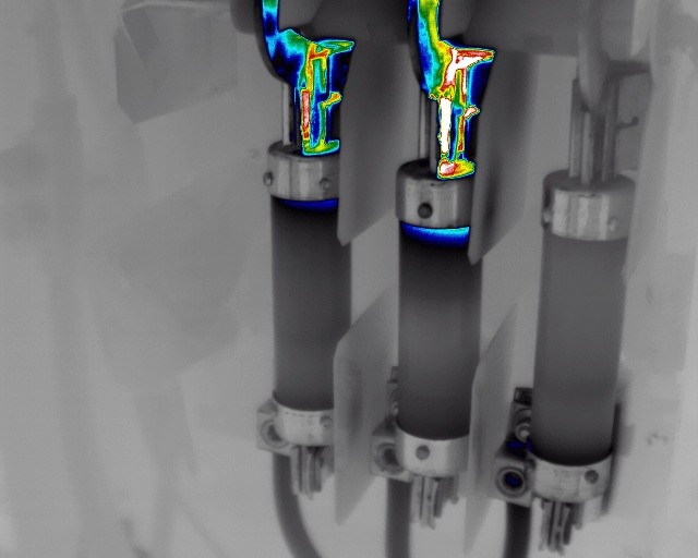
 Cable terminations and conductors in this motor control panel showing insulation breakdown due to heat cycling, vibration, and moisture exposure.
Insulation breakdown
Heat cycling, vibration, and moisture exposure gradually weaken insulation in conductors, busbars, and cable terminations.
Early-stage insulation degradation rarely triggers protection devices because the breakdown has not yet created a conductive fault path. It builds quietly until the material can no longer withstand operating voltage.

Damaged electrical connection showing heat and arc damage — localized resistance buildup leading to intermittent fault conditions.
Partial discharge in switchgear
Aging or stressed dielectric materials in switchgear can develop partial discharge activity that persists for extended periods before triggering a protection event. This degradation is difficult to detect without continuous monitoring.
Phase-level load imbalance
Uneven loading across phases stresses individual components disproportionately. One leg of a three-phase system may be running significantly harder than the others, creating thermal and electrical stress that does not surface when the system is evaluated at the panel level.
The common thread across all four mechanisms is intermittency. These faults develop under operating load, manifest under specific conditions, and disappear when those conditions change.
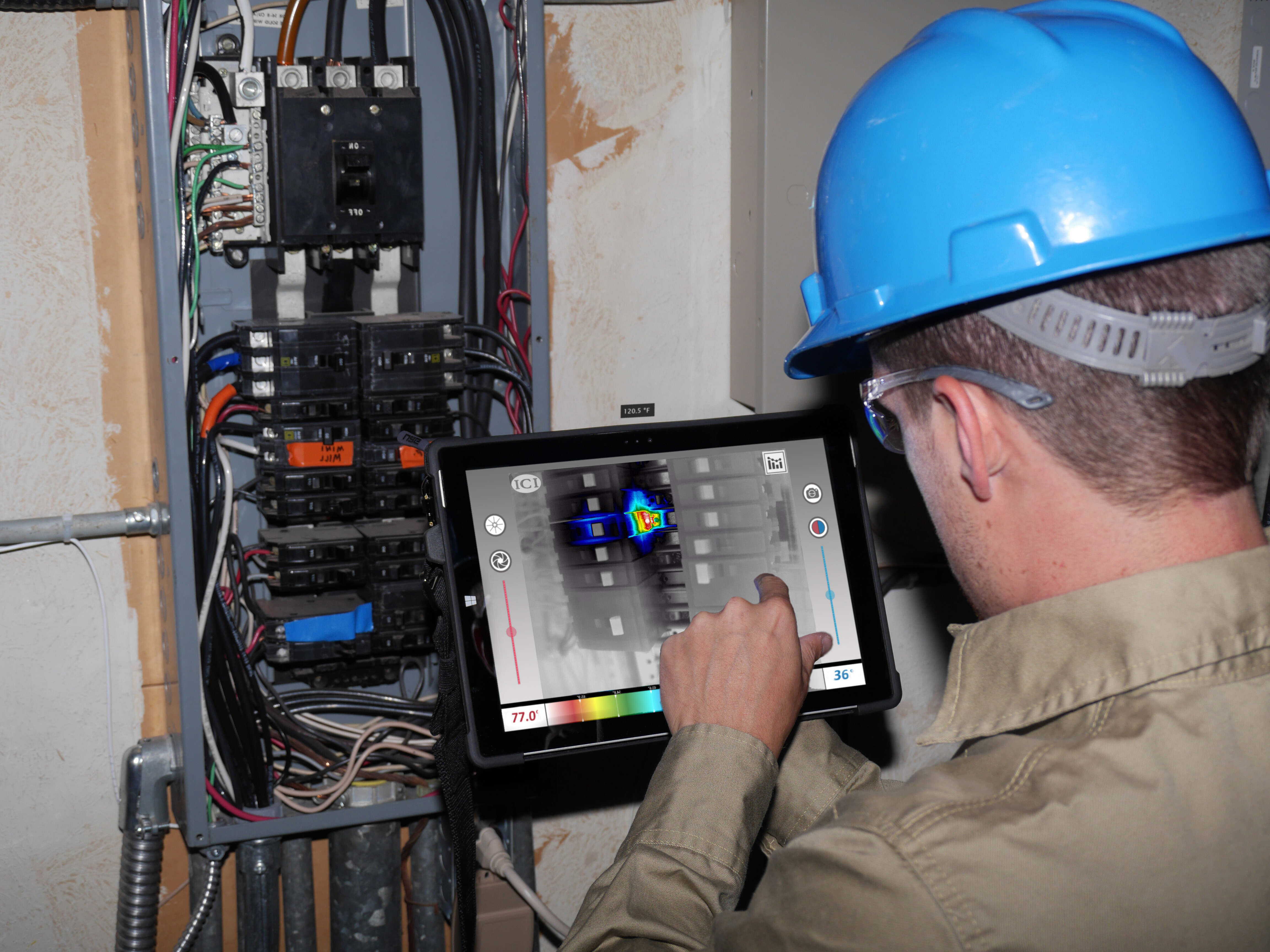
How Intermittent Faults Slip Through Scheduled IR Scans
Most facilities rely on periodic IR thermography as part of their electrical fault detection in motor control panels strategy, typically on a quarterly or annual basis.
These scans capture the thermal state of a panel at one point in time. If the fault is dormant at that moment, the scan comes back clean.
.jpg?width=761&height=609&name=0001_IR%20(1).jpg)
Thermal anomalies at electrical connections show intermittent hot spots that appear under load and disappear during scheduled IR inspections.
The timing problem
A terminal lug in an MCC section develops rising resistance. Under full operating load on a Tuesday afternoon, it generates measurable heat. By Saturday, when the facility runs at reduced capacity, the connection cools and the thermal signature drops below detectable levels.
A quarterly IR scan performed during a scheduled weekend outage captures a clean panel. Six weeks later, the lug fails under load.
The reset cycle
When a breaker trips and resets successfully, maintenance teams typically log it as a nuisance trip. The protection device did its job. The panel returned to normal. No visible damage.
But the underlying condition, the loose termination or developing insulation stress, has not been resolved. It will reappear the next time load and temperature conditions align.
This cycle can repeat for weeks or months before the fault progresses to functional failure: a breaker that will not reset, visible panel damage, or an arc flash event.
That progression is also where safety exposure is highest. The gap between a fault that trips and resets and a fault that escalates into an arc flash event or requires troubleshooting on an energized panel is the same gap that scheduled inspections are structurally unable to see.
The industry-wide gap
This detection gap is widespread. When NFPA 70B transitioned from a recommended practice to an enforceable standard in 2023, survey data from Schneider Electric found that 84% of facilities lacked the time and resources to comply.
Meanwhile, the ABB Value of Reliability survey found that over two-thirds of industrial businesses experience unplanned outages at least once a month, at an average cost of $125,000 per hour.
Periodic IR thermography is highly effective for detecting heat that is present and visible at the time of the scan. The limitation is specific: it was never built to track progressive degradation that develops under load, clears at rest, and reappears between inspection cycles.
Three Requirements for Detecting Load-Dependent Electrical Faults
If intermittent electrical faults develop under operating load and clear at rest, the detection approach has to align with how condition monitoring for electrical systems captures real operating conditions.
1. Continuous thermal monitoring under operating load
Capturing panel and MCC conditions during real-world operating states, including peak load, high ambient temperatures, and normal vibration, is the only way to observe fault conditions that appear and clear with the operating cycle.
A scan performed during a scheduled outage captures the panel in its most benign state. Continuous observation captures the panel in the state where faults are most likely to present.
2. Historical trending against established baselines
A single temperature reading tells you what a terminal is doing right now. It does not tell you where that reading sits relative to last week.
A lug running at 65°C may be operating within its normal range. A lug that was running at 55°C three weeks ago and has climbed steadily to 65°C is showing early signs of a developing fault.
Baseline deviation is a stronger early indicator of degradation than any absolute threshold.
3. Multi-signal context for confident interpretation
Temperature data becomes more meaningful when correlated with load data and time-of-day patterns.
A panel that runs hotter during peak production may be responding normally to increased demand. A panel that runs hotter at the same load level it handled last week may be developing a fault. The ability to distinguish between the two depends on having context around each reading, including load level, time of day, and recent trending history.
A concrete example shows why this is important. An MCC section feeding a sortation drive runs at 72°C during a peak Monday shift. That reading alone tells you very little. But if the same section ran at 63°C under the same load profile the previous Monday, and 67°C the Monday before that, the upward trend at consistent load is a meaningful early signal.
Now add time-of-day data. If the temperature rise correlates with afternoon shifts when ambient temperature climbs, the cause may be environmental. If the rise occurs consistently at the same load level regardless of ambient conditions or time of day, the cause is more likely internal: a connection degrading, insulation weakening, or resistance building at a terminal.
Without that layered context, a maintenance team is left with a single temperature number and no way to determine whether it represents normal operation, an environmental response, or a developing fault. Multi-signal context is what turns raw thermal data into an actionable early warning.
None of this eliminates the value of periodic IR scans. Those scans still serve a purpose for compliance and baseline documentation. But they cannot be the only layer of visibility into electrical assets that fail intermittently and develop under load.
Closing the Detection Gap Before It Becomes a Safety Event
Intermittent electrical faults in MCCs, motor control panels, and switchgear follow a predictable pattern. Rising resistance, insulation breakdown, partial discharge, and load imbalance all progress on their own timelines, driven by operating conditions.
Scheduled inspections capture a single moment. The gap between when degradation begins and when it becomes visible to a periodic inspection program is where most electrical failures live.
That gap is also where safety exposure is highest. Arc flash events and energized panel failures do not occur without prior warning signals. The warning signs were present, but they appeared at times and under conditions that no scheduled inspection was built to capture.

Electrical panel fault escalation. Undetected intermittent faults can lead to arcing, component failure, and safety events.
The Siemens True Cost of Downtime 2024 report found that unplanned downtime now costs the world’s 500 largest companies $1.4 trillion annually, up from $864 billion in 2019. For reliability teams managing electrical infrastructure in high-throughput operations, the cost of undetected degradation developing between inspection cycles continues to grow.
Failures inside MCCs, switchgear, VFDs, and electrical panels rarely happen without warning. The problem is that traditional inspection cycles often miss the early signs developing between checks. Continuous condition monitoring for electrical systems gives reliability teams the visibility needed to detect overheating connections, intermittent electrical faults, and degradation earlier — before they escalate into downtime, equipment damage, or safety incidents.
By combining continuous thermal monitoring, electrical fault detection, and multi-sensor condition intelligence, teams can move from reactive troubleshooting toward planned intervention. In high-throughput operations where even short disruptions carry significant operational and financial impact, earlier visibility is what protects uptime.
FAQ
Why do intermittent electrical faults in MCCs get missed during inspections?
These faults develop under operating load and clear when the load drops or the panel cools. A periodic IR scan captures one moment. If the fault is dormant during that moment, the scan returns a clean result.
Are quarterly IR scans enough to detect early-stage electrical degradation?
Quarterly scans are effective for detecting heat that is present and visible at the time of the scan. They serve a valid role for compliance and baseline documentation. They are less effective for faults that develop, manifest, and clear between inspection cycles.
What causes electrical faults in motor control panels?
The most common causes are loose or degraded connections at terminals and lugs, insulation breakdown in conductors and busbars, partial discharge in aging switchgear, and uneven phase-level loading. Each of these mechanisms progresses on its own timeline, driven by operating conditions like load cycling, vibration, and heat. The faults they produce are often intermittent, appearing under load and clearing at rest.
How do you detect intermittent electrical faults in MCCs?
Detecting intermittent electrical faults requires continuous thermal monitoring under actual operating load, not periodic snapshots during scheduled outages. Historical trending against established baselines helps surface gradual degradation that absolute thresholds miss. Correlating temperature data with load levels and time-of-day patterns provides the context needed to distinguish normal operating variation from a developing fault.
Interested in learning more about how to detect intermittent faults in your facility's MCCs? Book a technical session with the MSAI team. 👇

Keep reading
Condition Monitoring Blog Data Centers Electrical
Why Electrical Panels Overheat Under Normal Load — and a Six-Step Framework for Early Fault Detection
Condition Monitoring Blog Data Centers Electrical