Thermal Monitoring Condition Monitoring Blog Electrical
TL;DR — You Can Detect Control System Faults Without Accessing the PLC
Most control system faults don’t announce themselves in PLC logs. They show up first as subtle changes in electrical current, motor temperature, and mechanical behaviour. Those changes happen hours or days before the control system registers anything at all.
You don’t need PLC access to find them. You need continuous condition monitoring for electrical systems and the driven assets those systems control: visibility into the physical signals the PLC can’t see about itself.
The Problem: Conveyor Hesitation and Erratic Sorter Behaviour — But No PLC Fault
The conveyor hesitates on startup. A sorter drive cycles erratically. A VFD trips intermittently with no logged fault code. The PLC log is clean. “No fault found.”
This is one of the most common and costly diagnostic situations in high-throughput sortation environments. The system is clearly behaving abnormally, but formal diagnostics point to normal operation.
The frustration is real. So is the risk. Intermittent control system faults that go unresolved don’t stabilize on their own. They progress. A VFD with degrading capacitors continues to degrade. A loose connection in an MCC cabinet generating intermittent electrical noise doesn’t tighten itself. The fault that’s invisible today becomes the unplanned stoppage during a peak sort window.
The root cause of the diagnostic failure isn’t the controls team. It’s a structural limitation in where most facilities look for fault evidence.
Why PLC-Centric Troubleshooting Misses Early-Stage Degradation
PLCs Only Flag Threshold Breaches — Not Progressive Degradation
A PLC confirms when a defined condition has been breached. It does not track the gradual degradation leading up to that breach.
Motor current trending upward? Not visible. Cabinet temperature rising? Not in the logic. VFD output instability below threshold? Invisible.
The PLC is often the last place a fault appears—not the first.
A PLC is a logic controller, not a condition monitor. Its alarm architecture is built around threshold-based, pre-programmed fault states: drive fault, e-stop activated, sensor timeout. It confirms when a defined condition has been breached. It does not track the gradual degradation leading up to that breach.
Motor current trending upward over three weeks before a fault threshold is triggered? The PLC doesn’t see it. Cabinet temperature rising incrementally as a cooling fan loses efficiency? Not in the logic. A VFD output frequency fluctuating by fractions of a hertz as capacitors degrade? Below the alarm threshold, invisible to the system of record.
The PLC is often the last place a control system fault becomes visible, not the first.
Intermittent Faults Occur Below the Logging Threshold
Transient events are the hardest fault class to diagnose through PLC data alone. A loose terminal that generates electrical noise under thermal load may behave normally during off-peak hours and during any scheduled inspection. The event that causes a momentary hesitation, a missed sensor trigger, or an irregular actuation may last milliseconds. By the time a technician responds to a reported fault, the physical conditions that caused it have changed.
PLC logs capture state transitions. They don’t record the sub-threshold conditions that produce intermittent behaviour. A log showing “no fault” is an accurate record of what the PLC was programmed to look for. It says nothing about what the system was actually doing.
Organizational Bottlenecks Delay Root Cause Isolation
Even when controls access is possible, it’s rarely fast. In most sortation hubs and parcel facilities, PLC systems are maintained by specialized controls engineers: internal specialists, third-party integrators, or OEM service teams. Accessing the logic, interpreting it in context, and determining whether observed behaviour represents a developing fault requires expertise that sits outside the maintenance and reliability function.
The result is a diagnostic bottleneck: the reliability team suspects a control-related fault, the controls team doesn’t have a clear problem to investigate, and the issue continues developing in the gap between them.
What Continuous Monitoring Reveals Before the PLC Does
Control systems don’t operate in a closed software environment. Every command the PLC issues, every signal a VFD converts, every relay that closes or opens: these actions have physical consequences that are observable before they produce a fault state in the logic.
This is the diagnostic opportunity most facilities are missing.
VFD Instability Appears as Current Variability and Motor Temperature Drift
A variable frequency drive converting control commands into motor output is a precision electrical device. As capacitors age, as bus bar junctions develop resistance from thermal cycling, as cooling efficiency drops, the VFD’s output changes. Speed regulation becomes slightly less precise. Current draw becomes slightly more variable. Motor temperature trends upward at loads that previously produced stable operation.
None of these changes trigger an alarm. All of them are measurable with the right instrumentation.
Faulty I/O and Electrical Noise Create Detectable Thermal Patterns-1.jpg?width=5&height=4&name=0003_IR%20(1)-1.jpg)
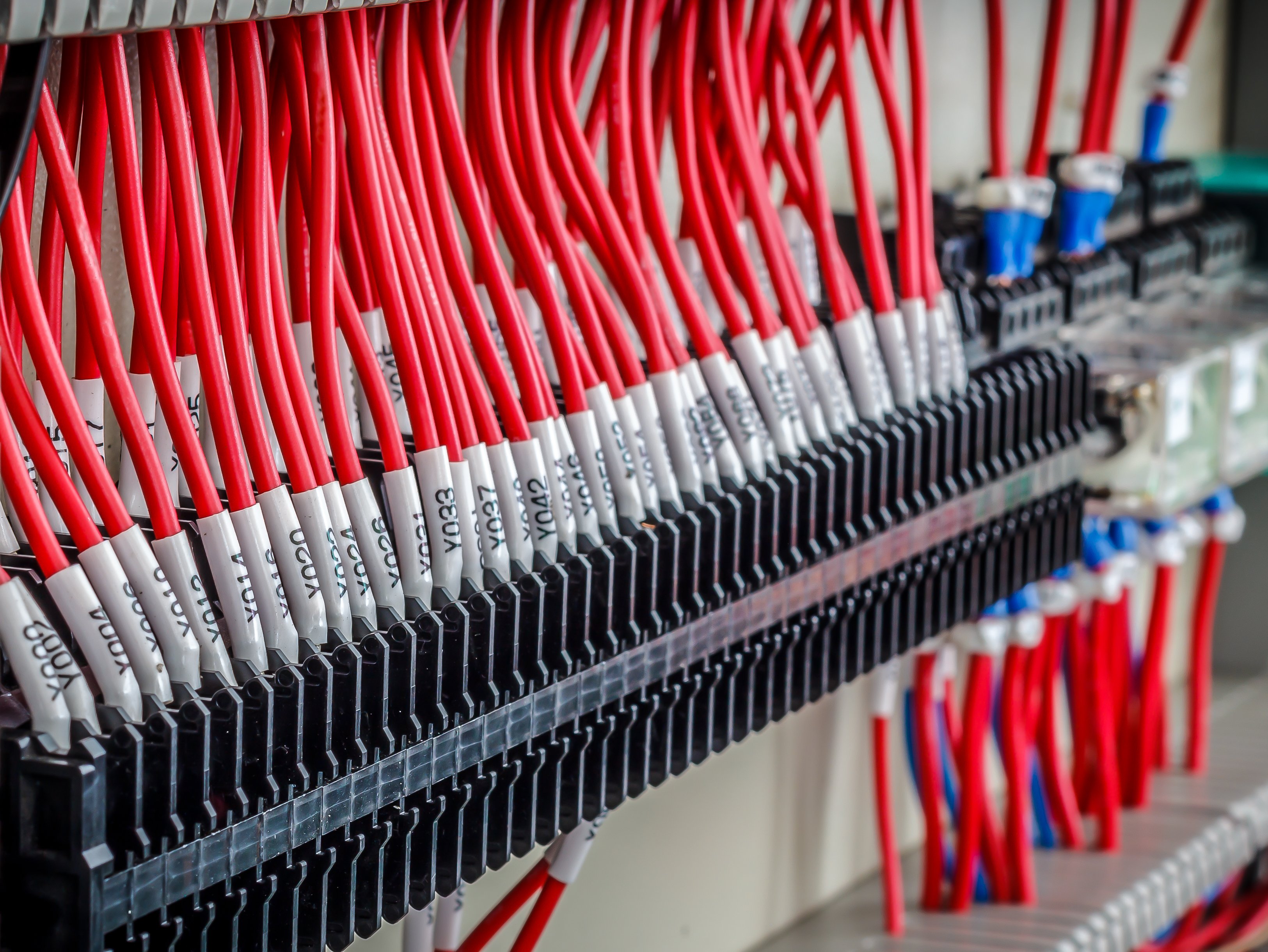
Control logic depends on clean signal transmission. Loose connections, degraded shielding, or high-resistance terminals in control wiring introduce noise that makes signal transmission unreliable. The result is commands that arrive late, trigger incorrectly, or fail to register, producing the hesitation, misfiring, and inconsistent cycling that operators report but PLC logs don’t capture.
The fault isn’t in the logic. It’s in the physical pathway the signal travels. Thermal monitoring of the control cabinet and electrical panels supporting that logic will detect the resistance-generating degradation before it produces intermittent failures.
Control Loop Oscillation Produces Distinct Mechanical Signatures
When a control loop loses stability because a drive is degrading, a sensor is drifting, or a feedback signal is introducing noise, the controlled equipment doesn’t respond smoothly. It hunts. It overcorrects. Conveyor drives accelerate and decelerate in micro-cycles that stress the mechanical drivetrain, produce inconsistent belt tension, and create the kind of irregular behaviour that gets attributed to mechanical causes while the actual source remains in the control architecture.

Vibration monitoring on the driven equipment detects this instability. The signature of a control-related mechanical oscillation is different from standard bearing wear, and the difference is diagnostically significant.
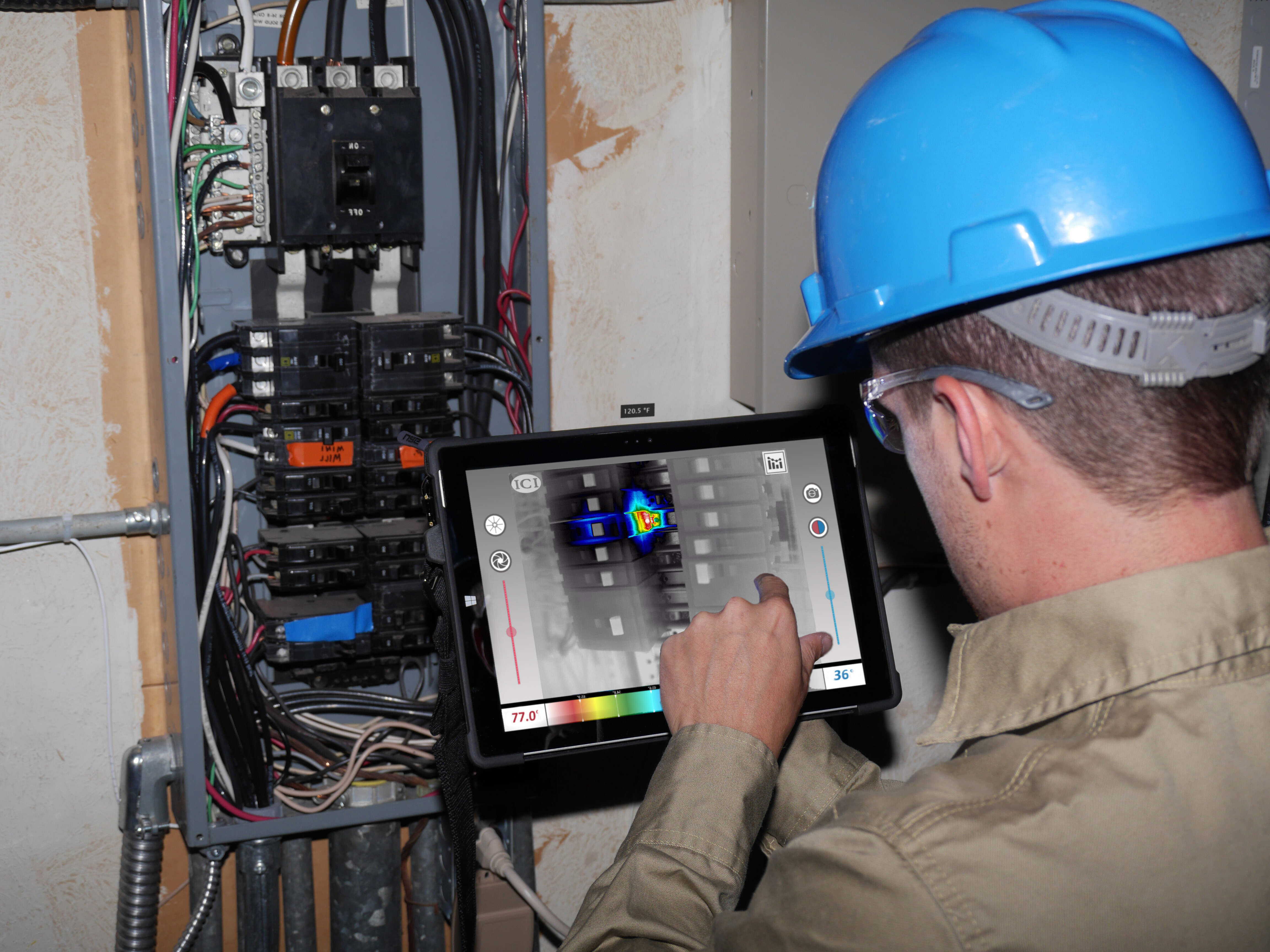
Electrical Degradation in MCCs and Panels Shows Up as Thermal Rise
MCC cabinets, VFD enclosures, and control panels contain the power and signal infrastructure that control logic depends on. Loose terminations generate resistance. Resistance generates heat. Heat accelerates insulation degradation. The cascade produces exactly the kind of intermittent, context-dependent faults that show up as erratic system behaviour with no logged cause.
 Thermal monitoring of this infrastructure detects the resistance-generating degradation as a rising temperature signature, typically 24 to 48 hours before it produces a breaker trip, a panel fault, or an intermittent signal loss.
What the Data Showed: A Real-World Example of Sub-Threshold Degradation
ChallengeA fulfillment centre operating a high-speed induction system begins experiencing intermittent conveyor hesitation on one zone. Operators report it. The controls team checks the PLC. The log shows no fault codes. The issue appears to resolve on its own for several days before recurring. Without external monitoring, the investigation stalls. The controls team has nothing actionable to investigate. |
SolutionWith continuous current monitoring on the VFD-driven motor for that zone, the picture changes immediately. The data shows small but consistent fluctuations in motor current draw, not large enough to trigger any alarm, but trending outside the established baseline over a ten-day window. Correlated with a thermal scan of the associated VFD enclosure, a warm spot on a bus bar junction confirms a developing high-resistance connection. |
ResultsThe maintenance team schedules a termination |

What Was Found: High-Resistance Connection Inside the VFD Enclosure
The approach is straightforward: instrument around the control system, not inside it. Monitor the physical signals that control system behaviour generates. Correlate those signals to identify developing fault conditions before they progress to operational impact.
The Result: Planned Repair Instead of a Peak-Window Conveyor Stoppage
Current variability, voltage irregularities, and power quality changes at the motor and drive level are among the earliest indicators of control system instability. A motor whose current draw is trending upward, or varying more than its normal operating baseline, is receiving power from a drive or control infrastructure that is degrading.
Continuous current monitoring on motors connected to VFDs and controlled by PLCs provides a real-time window into the electrical health of the entire control chain, without requiring access to a single line of PLC code.
Monitor Electrical Signatures on Driven Equipment
Vibration monitoring on driven assets (conveyor drives, sorter motors, induction system motors) captures how equipment responds to the commands it receives. Control-related instability produces mechanical signatures distinct from bearing wear or belt degradation: irregular speed patterns, micro-oscillations, inconsistent torque response.
These signatures are detectable. They are also actionable: the mechanical response anomaly points back toward the control source, giving the controls team specific evidence to investigate rather than an ambiguous fault report.
A Practical Framework: Detecting Control Faults Without PLC Access
Use Thermal Signals as Early Indicators for Condition Monitoring of Electrical Systems
Thermal monitoring is the most broadly applicable detection method for control system fault precursors. Almost every failure mode relevant to condition monitoring for electrical systems generates heat before it generates an alarm: loose connections, capacitor degradation, cooling fan decline, overloaded conductors.
Fixed thermographic monitoring on MCC cabinets, VFD enclosures, and control panels detects this thermal signature continuously. Deployment data shows this approach identifies hot spots 24 to 48 hours before a breaker trip or panel fault, converting potential emergency repairs into planned interventions, with documented avoided downtime costs of $12K–$24K per incident.
Correlate Signals Across Thermal, Current, and Vibration
Single-sensor anomalies can have multiple explanations. An elevated motor temperature could indicate bearing degradation, overload, or drive instability. A current variability signal could reflect mechanical load changes or electrical supply issues.
Multi-sensor corroboration narrows the diagnostic field. When a motor shows current variability and its associated VFD cabinet shows a thermal deviation and the driven equipment shows mechanical oscillation, the corroborated pattern points toward the control system with a confidence that no single signal source could provide.
This is the diagnostic advantage that condition monitoring built around multi-sensor signal fusion provides over PLC-only troubleshooting: not just more data, but correlated data that reduces ambiguity and enables faster, more confident intervention. See how MSAI Connect detects drive and control faults across sortation and distribution environments.
Why Multi-Sensor Condition Monitoring Outperforms PLC Logs Alone
There is a fundamental distinction between what PLC data records and what sensor-based monitoring captures.
PLC data reflects intended behaviour: what the control logic commanded, what threshold states were reached, what fault conditions were logged.
Sensor data reflects actual behaviour: what the motor did, what temperature the cabinet reached, how the drive’s electrical output varied. It captures the gap between the commanded state and the executed state, and that gap is precisely where early-stage control system faults live.
When a degrading VFD outputs a slightly irregular frequency that the motor follows imperfectly, the PLC records a command. Continuous monitoring records what actually happened. The difference between those two records is the detection window that allows intervention before failure.
Across deployments in high-volume fulfillment centres and parcel sortation hubs, this approach has prevented conveyor stoppages costing ~$18K in labor-related impact, avoided ~4 hours of downtime producing ~$24K in operational exposure, and delivered full ROI within approximately one month of deployment.
Those outcomes weren’t driven by faster reaction. They were driven by earlier detection — identifying electrical and control degradation while it was still correctable within a planned window rather than during a peak shift. Multi-sensor monitoring doesn’t replace PLC diagnostics. It gives the controls team physical evidence of the conditions that produced the problem, captured in real time, before the fault state was reached.
Learn how the MSAI Connect condition monitoring platform delivers that visibility across drives, panels, and MCC infrastructure.
A Practical Framework for Early Detection
- Stop treating the PLC as the only source of truth. The PLC is accurate about what it’s designed to detect. It has no visibility into the physical degradation that produces control system instability. Expand the diagnostic picture beyond control logic.
- Instrument around — not inside — the control system. Focus on the physical assets the control system drives and the infrastructure it depends on: motors, VFD enclosures, MCC cabinets, control panels, and the driven mechanical equipment.
- Monitor continuously, not periodically. The failure modes that produce intermittent control system faults develop on timescales of hours to days: thermal rise from loose connections, capacitor degradation, drive output variability. Weekly or monthly inspection routes cannot intercept them reliably.
- Correlate signals to identify control-related patterns. Electrical anomaly plus mechanical response plus thermal deviation is a pattern. Any single signal is a data point. The combination is a diagnosis.
- Escalate with evidence, not guesswork. When the controls team receives a report showing a VFD cabinet temperature trending 12°C above baseline over five days, correlated with current variability on the associated motor, they have a specific, locatable fault to address. Evidence-based escalation compresses the diagnostic cycle.
Where This Approach Delivers the Most Value
The facilities that benefit most from external, continuous monitoring of control system fault precursors share a common profile.
- Fulfillment centres and sortation hubs with limited PLC access. Where control logic is managed by third-party integrators or OEM service teams, detecting faults through physical signals compresses response time and reduces dependence on the diagnostic bottleneck.
- Legacy systems with undocumented control logic. External signal monitoring provides fault detection that doesn’t depend on understanding the logic. It observes what the system does, not how it was programmed.
- High-throughput parcel facilities where downtime is costly. Detecting a degrading VFD five days before it fails converts a potential four-hour emergency repair into a planned component replacement. That’s the difference between a controlled intervention and a stoppage that idles labor across the entire sort floor.
- Operations with recurring “no fault found” situations. If your facility has experienced repeated incidents where equipment behaves abnormally and controls diagnostics find nothing, the fault is real, below the PLC’s detection threshold, and progressing.
FAQ: Detecting Control System Faults Without PLC Access
Can you really diagnose PLC-related issues without accessing the PLC?
Yes. By observing how the system behaves physically rather than what the control logic records, the physical consequences of control system degradation (electrical variability, thermal rise, mechanical instability) are observable and measurable independently of PLC access. The goal is not to read the PLC; it’s to detect the physical conditions the degrading control system produces.
Why don’t PLCs catch these issues themselves?
PLC alarm logic is threshold-based and pre-programmed. It detects defined fault states: conditions that cross a programmed threshold or match a defined error code. Gradual degradation that hasn’t yet reached a threshold, intermittent faults that resolve before a log entry is written, and sub-threshold instability that produces operational problems without triggering defined conditions are all invisible to the PLC by design.
What’s the earliest sign of a developing control system fault?
Thermal deviation in the associated control infrastructure is typically the earliest detectable indicator. Loose connections, degrading capacitors, and cooling system decline in VFD enclosures and MCC cabinets all produce measurable thermal signatures before they produce electrical faults or operational symptoms. Current variability on driven motors is the next earliest indicator, detectable before mechanical or operational effects become apparent.
Is this approach a replacement for PLC diagnostics?
No. It’s a complement that makes PLC diagnostics more effective. External signal monitoring surfaces the physical evidence of developing control system faults. That evidence gives the controls team a specific, locatable, time-stamped fault condition to investigate rather than an ambiguous symptom report.
What’s the most common mistake teams make when dealing with intermittent control faults?
Waiting for the fault to become consistent enough to capture in a PLC log. Intermittent faults that don’t produce logged errors are easy to deprioritize, and the “no fault found” response creates organizational pressure to move on. The physical degradation driving the intermittent behaviour continues to progress in the meantime. The cost of waiting is paid when the fault advances beyond intermittent to operational, typically at the worst possible moment.
Closing the Visibility Gap Between Control Logic and Physical Reality
Control systems leak signals into the physical world. Those signals are detectable, continuous, and when properly instrumented and correlated, they provide the early warning that PLC alarms cannot.
The maintenance and reliability teams who close this gap operate with a concrete advantage: they find developing control faults before the controls team has been called, before the fault log has an entry, and before the operational event has occurred. In high-throughput environments, that lead time is the difference between a scheduled repair and a four-hour stoppage with labor stand-down across the sort floor.
That’s not a controls engineering capability. It’s a condition monitoring capability, and it’s available without touching the PLC.
Interested in how continuous multi-sensor condition monitoring detects electrical and control system fault precursors in sortation and fulfillment environments? Book a technical session with the MSAI team. 👇

Keep reading

MSAI Connect Thermal Monitoring Condition Monitoring Blog Vibration
You Have Condition Monitoring—But Here's What It's Probably Missing
Condition Monitoring Blog Data Centers Electrical