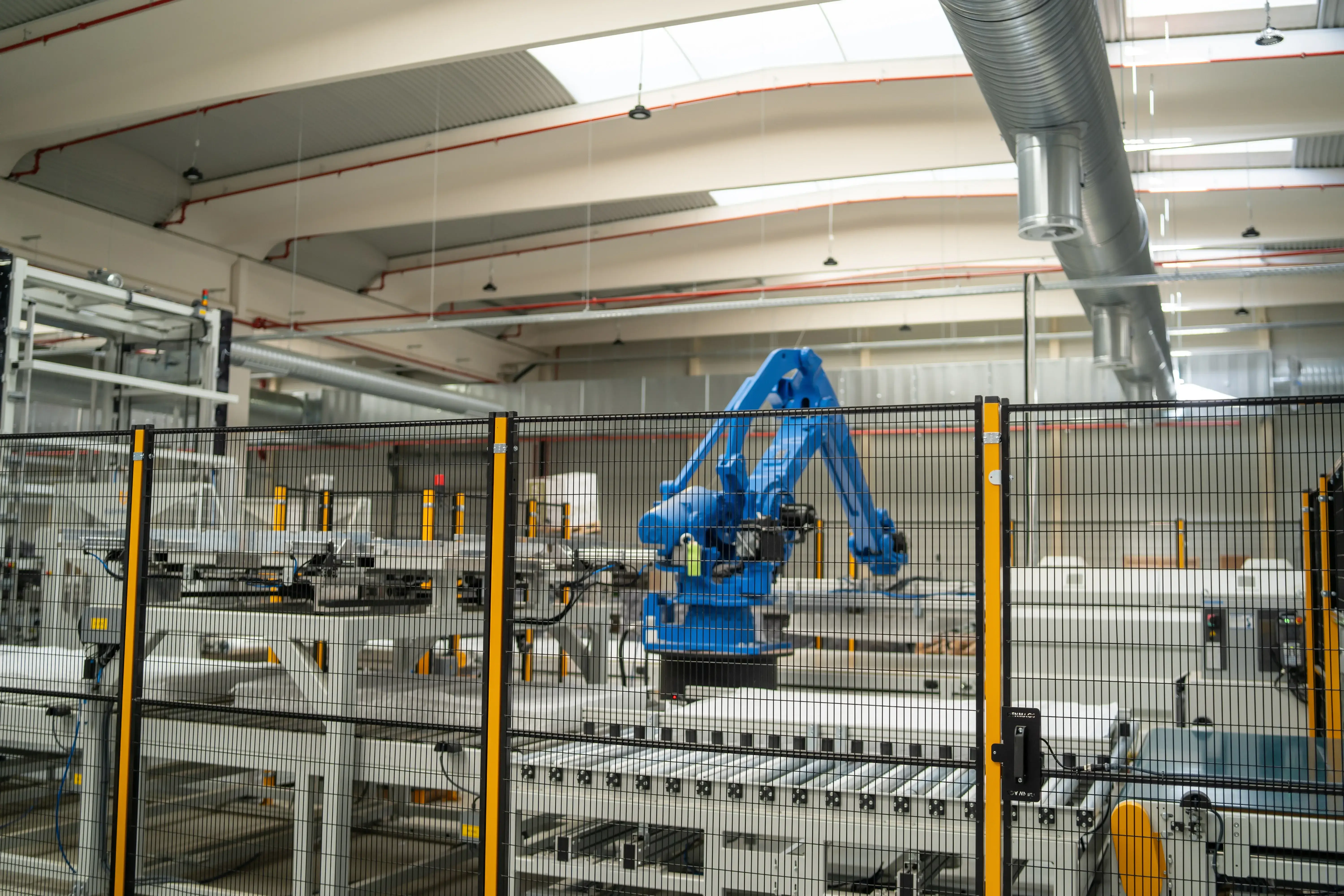
TL;DR:
Most industrial failures are not truly sudden. Motor degradation, pick and place misalignment, overheating electrical connections, and control faults often develop silently between inspection cycles.
Continuous condition monitoring helps reliability teams detect these issues earlier through:
- thermal monitoring,
- vibration condition monitoring,
- electrical condition monitoring,
- and multi-sensor corroboration across conveyors, MCCs, motors, VFDs, and switchgear.
This creates an earlier intervention window so teams can plan corrective action before failures escalate into downtime, emergency repairs, or operational disruption.
A robotic fault without alarm is not a random event
It was 2 AM, the robotic arm was frozen mid-cycle, the line was down, and this was a classic robotic fault without alarm; not a single alert had fired to explain why.
The maintenance team had been through three days earlier and found nothing worth flagging. The previous shift had run completely clean. Four hours of throughput disappeared before anyone understood what had actually gone wrong, or why nothing caught it before it did. A robotic fault without alarm is not a random event; it is the final stage of a degradation progression that fault codes and maintenance schedules were never designed to catch.
If you manage automation in a warehouse sortation system, a fulfilment robotics cell, or an automated picking line, you have either lived through this exact scenario or something close enough that it feels familiar.
The frustrating part is not the failure itself, but the way it stays with you. It is the realization that the failure did not happen suddenly. The servo drive degradation symptoms were there. The signals were measurable. The degradation had been progressing for days, quietly building inside a drive cabinet that looked completely fine at last check. And nothing caught it, not the fault codes, not the maintenance schedule, not the single-sensor alarm.
That gap between what was happening and what your systems could see is what keeps experienced automation engineers up at night. It should. Because it is not an inexplicable fluke. It is structural.
That is not a maintenance failure. That is a visibility gap in how most automation environments are designed to detect degradation. Understanding why robotic cells fail between maintenance cycles is the first step toward closing the gap.
How Servo Drive and VFD Degradation Actually Progresses
Servo drive degradation and VFD failure before the fault code are not sudden events. They are progressive. The failure you see at 2 AM started well before then, often hours to days earlier. It develops through a sequence of physical changes that are entirely measurable, if you are observing the right signals.
Early Thermal Signs of Servo Drive Failure
Servo drives degrade through several overlapping mechanisms. Heat accumulation is typically the earliest and most consistent indicator of servo drive degradation. Insulation resistance in motor windings begins to break down over time. Thermal cycling, duty-cycle intensity, and age all contribute.
As that breakdown progresses, the drive starts generating localized thermal increases inside the cabinet. These increases tend to concentrate around power modules or bus bars. This thermal rise can precede a fault code by 24 to 72 hours, sometimes longer. These are classic servo drive degradation symptoms. They are not invisible. They are simply unobserved because no fixed continuous sensor is watching for them.
How VFD Electrical Faults Develop Before Operational Failures Appear
VFD failure before fault code follows a similar pattern. The early signals, however, manifest slightly differently. A VFD under variable load in a sortation system or automated picking line will often begin showing subtle changes in harmonic distortion and current draw. This happens well before any visible performance degradation occurs.
The drive continues to function. Cycle times look normal. But the electrical signature is shifting. That shift is a measurable early indicator of developing stress on capacitors, power modules, or cooling components inside the drive enclosure. This is exactly the kind of VFD failure before fault code scenario that periodic maintenance is not designed to catch.
.jpg?width=1920&height=1080&name=Untitled%20design%20(6).jpg) Thermal monitoring view of electrical infrastructure showing temperature increase at connection point.
Thermal monitoring view of electrical infrastructure showing temperature increase at connection point.
How Robotic Axis Degradation Develops Before Alarm Thresholds Trigger
Robot axis fault detection is where the gap becomes particularly acute. A robotic arm in a fulfilment cell might complete its full motion cycle with no visible error. But if you are trending positional timing data, you will often see microsecond deviations from the established baseline. Those deviations indicate early bearing wear, encoder drift, or subtle mechanical misalignment. The robot finishes its cycle. The system logs no alarm. This is a robot fault without alarm in its clearest form.
The deviation from baseline is there, and it is growing. By the time it crosses the threshold that triggers a servo drive fault code or axis error, the intervention window has already compressed significantly.
Robotic cell instability causes are rarely singular. Instability develops from a combination of signals building at the same time. The drive cabinet is running warm. A VFD showing torque ripple under load. An axis drifting from its timing baseline. Cabinet ambient temperature is climbing in a cell running at or near duty-cycle limits during peak throughput windows. Each signal, on its own, looks manageable. No single one crosses a threshold. But together, they describe a system that is clearly moving toward failure. The problem is that most detection architectures are only looking at each signal in isolation.
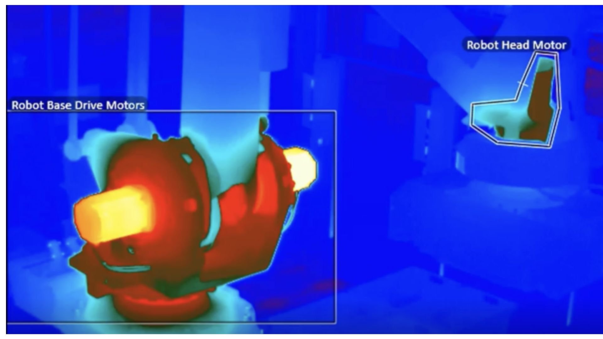
Thermal monitoring of robotic drive motors revealing localized heat buildup and early-stage degradation that may not trigger alarms or fault codes during normal operation.
Why Fault Codes and Scheduled Maintenance Are Structurally Designed to Miss Failure Between Cycles
Fault codes and periodic maintenance are not bad methods. They are well-designed methods, built for a specific purpose. That purpose, however, is not early degradation detection. Understanding that distinction matters. It explains why robotic cells fail between maintenance cycles even when teams are doing everything right by detecting the effect and not the cause.
Fault Codes Report Failure, Not Progression
Fault codes are designed to protect equipment. They trigger at defined thresholds: temperature limits, overcurrent conditions, and position error maximums. These thresholds represent the point at which the drive or controller needs to halt operation to prevent damage. By design, the fault code fires at the end of the degradation window, not the beginning.
A VFD overtemperature alarm tells you the drive has already reached a critical thermal state. It does not tell you the thermal drift started 48 hours ago. It does not tell you the pattern was visible in the trending data long before the threshold was crossed. The fault code confirms a failure condition. It does not detect a developing one – and that’s why most reliability programs still detect failures too late. VFD failure before fault code is, by definition, invisible to a threshold-based alarm system.
Scheduled Maintenance Captures Snapshots, Not Trends
A quarterly inspection. A monthly thermography walkdown. A biweekly checklist. Each of these captures the system state at a single moment in time. A servo drive running within spec on Monday morning can be running 12 degrees above its baseline thermal profile by Thursday afternoon. This is especially likely in cells operating at or near duty-cycle limits during high-throughput windows. The inspection does not close that gap. It simply creates a false sense of coverage between touchpoints. The servo drive degradation symptoms that develop between visits go completely unrecorded. In a high-throughput fulfilment environment, that unrecorded window is where line stoppage events and SLA exposure are born.
Scheduled maintenance is only as accurate as the time it is taken. The moment you walk away it is out of date.
Luke Grice-Lowe, Reliability Engineer
Why Historical Alarm Data Often Lacks Operational Context
When a fault code fires without continuous historical context, it is almost impossible to know whether the condition developed suddenly or had been building for days. A fault log entry tells you when the system crosses the threshold. It does not tell you the slope of the degradation curve that got it there. That slope is precisely the information you would need for proper robot axis fault detection before the next incident.
The result is a Visibility Gap: the window between the point when early degradation signals become measurable and the point when a fault code finally fires. In highly automated warehouse and fulfilment environments, that gap is where robotic cell instability causes most unplanned downtime events.
How to Actually Detect Early Robotic Cell Degradation
Catching robotic cell degradation and closing the visibility gap does not require replacing what you already have. It requires adding a different kind of observation, one that is continuous, multi-signal, and baseline-referenced rather than threshold-triggered. Three principles define what genuine robot axis fault detection looks like in practice.
1. Continuous Thermal Observation Inside Drive & Electrical Cabinets
Servo drive degradation symptoms, and VFD failure before fault code are thermal stories. They develop over hours or days. Fixed continuous thermal monitoring inside drive cabinets and at motor housings captures that progression in real time. A thermal reading taken during a monthly walkdown is a single data point. Continuous thermal trending over 72 hours is a pattern. Patterns are where early signals live. Knowing a drive is currently at 68 degrees tells you one thing. Knowing it has been climbing 0.4 degrees per hour for three days tells you something entirely different. The second reading is an early servo drive degradation signal. The first is just a snapshot.
2. Multi-Signal Context: What No Single Sensor Can Resolve Alone
Thermal monitoring alone misses vibration anomalies that indicate bearing wear in servo motors. Vibration monitoring alone misses the thermal drift inside a drive cabinet that precedes a fault code. Fault-code monitoring alone misses both. When you correlate cabinet thermal trending with vibration signatures and motor current draw, simultaneously and across the same asset., you start surfacing robotic cell instability causes that no individual signal can identify on its own. A VFD running warm and showing subtle torque ripple under variable load is a more actionable early signal than thermal or vibration monitoring could provide in isolation. That kind of multi-modal correlation is what separates genuine early detection from false confidence or false positives.
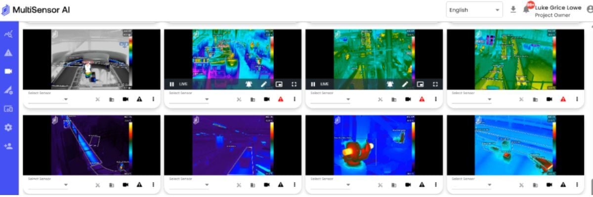
3. Baseline Deviation: Why Relative Change Matters More Than Absolute Temperature
Robotics faults without alarm scenarios are rarely about a single sensor reading a high absolute value. They are about a specific asset deviating from its own established operating baseline. The asset's load profile and environment matter. Knowing that a servo drive is running 18 degrees above its established operating baseline is more useful than knowing its absolute temperature. It tells you something has changed relative to normal for that specific asset. Baseline deviation detection, referenced to the individual asset rather than a generic specification, is where the early intervention window opens and where true robot axis fault detection begins.
These three principles represent a shift in mental model: from responding to fault codes to observing continuous deviation from baseline. That shift is what separates teams that get surprised by robotic cell instability from teams that see it developing and act before the line stops.
4. The Bottom Line: Automation and Robotics Faults Aren’t Sudden
Automation and robot fault without alarm events keep surprising maintenance teams because while the degradation is not sudden, the detection systems are. Fault codes, periodic maintenance schedules, and single-sensor monitoring all share the same design limitation: they were built to report failure, not to catch the progression toward it.
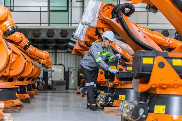
Robotic fulfillment and sortation systems can develop drive, axis, and control instability long before a fault code triggers an alarm.
The servo drive degradation symptoms are real. The early VFD failure before fault code signals are measurable. The robot axis fault detection window exists before the alarm ever fires. The question is simply whether your detection architecture gives you visibility into it before the fault code fires and the cell goes down.
Understanding the structural shape of the gap is the starting point. Closing it requires more than better sensors or more frequent inspections. It requires an intelligence layer that sits above your existing systems, continuously correlating signals, tracking deviation from baseline, and surfacing degradation patterns before any single threshold is crossed. That is a different architecture. And getting there starts with a framework.
FAQ
What is condition monitoring?
Condition monitoring is the continuous or periodic measurement of equipment health to identify signs of degradation before functional failure occurs. It commonly includes thermal monitoring, vibration analysis, electrical monitoring, and visual inspection across motors, conveyors, switchgear, bearings, VFDs, PLCs, and other critical assets.
What is condition-based monitoring?
Condition-based monitoring (CBM) is a maintenance approach where maintenance activity is triggered by actual real-time equipment condition, rather than fixed inspection schedules or calendar-based intervals.
Instead of replacing components on a predefined timeline, teams intervene when monitored signals indicate developing degradation or abnormal operating conditions.
Why do failures still feel sudden in automated operations?
Many failures appear sudden because degradation often develops invisibly between inspection cycles. In high-throughput environments, detection windows may compress from weeks to days or even hours.
Loose electrical connections, overheating terminals, bearing wear, conveyor misalignment, lubrication breakdown, and VFD instability can progress rapidly without triggering obvious alarms until disruption occurs.
Why are periodic inspections no longer enough?
Periodic inspections only capture equipment condition at the exact moment the inspection occurs. Fast-developing or intermittent faults may remain undetected between inspection routes.
As industrial systems become more automated and uptime-dependent, relying exclusively on manual walkdowns creates operational visibility gaps that increase exposure to downtime and reactive maintenance events.
What types of failures can multi-sensor condition monitoring detect?
Multi-sensor condition monitoring can help detect:
- motor bearing degradation
- conveyor belt misalignment
- electrical resistance heating
- overloaded circuits
- switchgear overheating
- VFD degradation
- PLC and control panel instability
- cooling system anomalies
- fan and pump imbalance
- lubrication breakdown
- and intermittent automation faults
- schedule repairs during planned downtime windows
- reduce emergency callouts
- prioritize maintenance based on actual asset conditio,
- reduce unnecessary preventive maintenance
- improve spare parts and labor planning
- e-commerce and retail distribution
- couriers and parcel operations
- airport baggage handling
- cold storage and food warehousing
- data centers
What is multi-sensor condition monitoring?
Multi-sensor condition monitoring combines multiple data sources — such as thermal, visual, vibration, acoustic, and environmental signals — into a unified detection system.
Rather than relying on a single alarm source, multi-sensor corroboration helps reduce false positives and improves confidence in alerts by validating degradation patterns across multiple signal types simultaneously.
How does continuous condition monitoring improve maintenance planning?
Continuous monitoring provides earlier visibility into developing degradation, allowing maintenance teams to:
What industries benefit most from continuous condition monitoring systems?
Condition monitoring systems are especially valuable in highly automated, uptime-critical industries, including:
These environments often contain single-point-of-failure assets where even short disruptions can create significant throughput loss and operational impact.
Does condition monitoring replace CMMS or SCADA systems?
No. A condition monitoring platform operates as an intelligence layer above existing systems. It augments CMMS, SCADA, PLC, and BMS environments by providing earlier degradation visibility and alerting, but it does not replace maintenance management or control systems.
What is the difference between threshold alarms and early degradation detection?
Traditional threshold alarms activate only after a condition exceeds a predefined limit. Early degradation detection focuses on identifying subtle deviation patterns before those thresholds are reached.
This allows teams to detect progressive failure modes earlier — especially issues that evolve gradually across motors, conveyors, electrical systems, and automation infrastructure — before a failure occurs.
Keep reading

Thermal Monitoring Condition Monitoring Blog
How We Taught Solar Monitoring to Stop Mistaking Reflection for a Fault

Condition Monitoring Reliability Engineering Blog